User guide for nanoMoCo, MoCoBus, and the new Motion Engine
The following user guide can also be found at the site of http://www.dynamicperception.com. The nanoMoCo stepper driver/controller is a specialized, Arduino-compatible* device specifically designed to enable advanced multi-axis stepper-based robotics and automation projects less expensive, and easier to create.
Key features of the nanoMoCo include:
- Atmega328P processor running at 16MHz
- 8-16V DC Operation
- Integrated A4983/A4988 bi-polar chopping driver with up to 16x microstepping
- Up to 800 mA/coil without active cooling
- Up to 1.5 A/coil with active cooling
- Dual opto-coupled outputs for safe interaction with other devices
- Integrated RS485 bus for multi-node communication over long distances with only two wires
- Pre-installed bootloader to allow for uploading firmware over RS485 bus
- Compatible with Arduino IDE and AVRDude
- Pre-installed Motion Engine firmware for expressive motion control using MoCoBus
- Leverage the OpenMoCo AVR Libraries and OpenMoCo Qt Libraries to create new software and applications
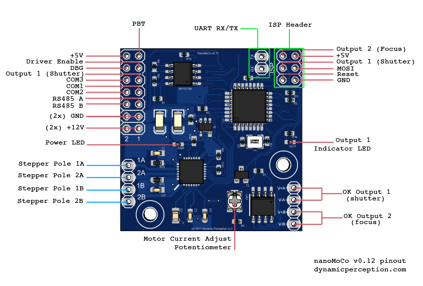
nanoMoCo Pin Function
The following table describes the output pins, and their functions on MoCoBus:
| nanoMoCo pin | Function |
|---|---|
| Stepper Pole 1A | Stepper motor Pole #1, Lead A |
| Stepper Pole 2A | Stepper motor Pole #2, Lead A |
| Stepper Pole 1B | Stepper motor Pole #1, Lead B |
| Stepper Pole 2B | Stepper motor Pole #2, Lead B |
| OK Output 1 | Opto-coupled Output #1, Used as shutter control in default firmware |
| OK Output 2 | Opto-coupled Output #2, Used as focus control in default firmware |
| +12V | +12VDC power input |
| GND | Common Ground |
| RS485 B | RS485 Bus Channel B |
| RS485 A | RS485 Bus Channel A |
| COM 1 | MoCoBus Common Line #1 |
| COM 2 | MoCoBus Common Line #2 |
| COM 3 | MoCoBus Common Line #3 |
| Output 1 | Non-opto-coupled version of OK output #1, for monitoring |
| Output 2 | Non-opto-coupled version of OK output #2, for monitoring |
| DBG | Debug line output |
| Driver Enable | Driver Enable line, for monitoring stepper driver state |
| +5V | +5VDC |
| PBT | Pushbutton I/O Line |
| MOSI | Master out, slave in - for ISP and GPIO purposes |
| Reset | Atmega328p RESET line |
Arduino Pin Mapping
The following table shows all pins from the standard Arduino Atmega328p interface to the nanoMoCo pins and assignments:
| Arduino pin | nanoMoCo pin | Function |
|---|---|---|
| D0 | RX, RS485 | UART Receive |
| D1 | TX, RS485 | UART Transmit |
| D2 | Common 1 | MoCoBus Common Signal #1 |
| D3 | Common 2 | MoCoBus Common Signal #2 |
| D4 | n/c | Motor Driver Direction Signal |
| D5 | n/c | RS485 Driver Enable |
| D6 | n/c | n/c |
| D7 | PBT | GPIO |
| D8 | n/c | n/c |
| D9 | n/c | Motor Driver Step Signal |
| D10 | n/c | n/c |
| D11 | MOSI | GPIO |
| D12 | Output 2 | Focus control / GPIO / Opto-coupled output |
| D13 | Output 1 | Shutter control / GPIO / Opto-coupled output |
| A0 | n/c | Motor Driver MS1 |
| A1 | n/c | Motor Driver MS2 |
| A2 | n/c | Motor Driver MS3 |
| A3 | Driver Enable | Motor Driver Enable |
| A4 | DBG | GPIO |
| A5 | Common 3 | MoCoBus Common Signal #3 |
The nanoMoCo driver/controller board can operate with any bi-polar stepping motor that can run on 8-16V of input. Typically, on MoCoBus arrangements, only 12V motors are used. Any stepping motor with at least 4 wires, and an even count of wires (4, 6, 8) can be wired bi-polar. Consult the data sheet for your motor for the correct wiring diagram.
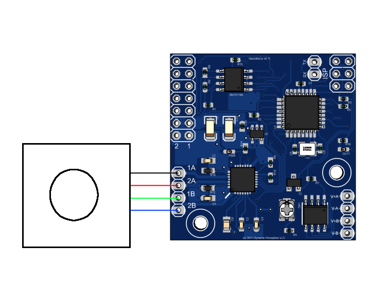
Connecting the Motor
The following diagram indicates a standard bi-polar stepper motor wiring to the nanoMoCo. Again, please consult with the data sheet for your motor for the correct wiring. Manufacturers may use the same color wires for different purposes.
Tuning the Motor
The motor driver must be tuned to the correct current limit for your motor. Failure to do so will result in erratic movement, under-powering, or over-heating of the motor. The current adjustment potentiometer can be adjusted with a small flat-tip or phillips screw driver.
If you're using the standard Motion Engine firmware that the nanoMoCo comes with, it's worth noting that the default behavior of the firmware is to sleep the driver (disable it) between moves. In this case, you must either perform your tuning in the first 8 seconds after booting up, or using a software client like Graphical Slim - adjust the current during a movement, or disable the sleep setting. You may also create your own firmware using the OpenMoCo AVR libraries, and using OMMotor to set the driver to disable sleeping.
The easiest way to adjust the current draw is with a benchtop power supply that shows a current read-out, allowing you to adjust the current until the correct load is shown. Alternatively, you may make a very long move of the motor, and tune it until the motor moves smoothly and with the correct amount of torque.
Note that the potentiometer has stops at both ends of its motion, do not attempt to turn it past these stops or you may damage the potentiometer.
Connecting to the MoCoBus
Following the standard MoCoBus design, you may connect up to 32 nanoMoCo devices on a single bus. A bus is a chain of directly connected devices, in the case of MoCoBus, there are two actual buses used - one 2-wire, balanced RS485 bus for command and control, and 4-wire Simple Synchronization bus.
If you're simply using one nanoMoCo device and one controller, in most cases you'll only need the two wires for the RS485 command and control bus. A RS485 is balanced, it does not require a ground signal.
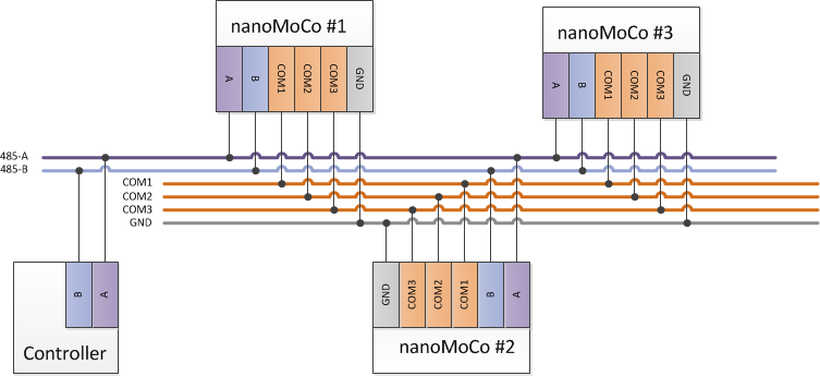
If you're using two or more nanoMoCo devices (or any other MoCoBus devices), then you'll want to take advantage of the Simple Synchronization bus if you want the devices to act in concert. While not required, this allows nodes on the MoCoBus to work together autonomously, without constant control from a connected master device (such as a controller or computer). The three control lines on the Simple Synchronization bus are referred to as Common 1, 2, and 3. A fourth wire, a common ground, is required to utilize these lines.
The following diagram shows how three nanoMoCo devices and one master device would be wired together using these buses:
RS485 Termination
When using just one or two devices on a short run of cable, it is usually not necessary to terminate the RS485 bus. However, for reliable operation in the field it is recommended to terminate the bus at the last node and at the controller. This is achieved by installing a 120 Ohm resistor between A and B at the final device in the chain, and at the controller. This prevents the signal from echoing back on the bus.
Cabling Selection
In accordance with the RS485 (EIA485) specification, twisted pair wiring must be used for external cabling on the command and control bus. We also suggest using twisted cabling for the Simple Synchronization bus as well.
The standard choice in interconnect cabling for MoCoBus is CAT5e or better ethernet cable. It is ubiquitous, easy to source, and the RJ45 connection standard on ethernet cables provides a locking mechanism to prevent accidental disconnect. One should always choose "patch"-style cabling, that is - the pin out is the same on both connectors on the cable. Do not choose "crossover"-style cabling, where the pinout is crossed between the two connectors.
The following indicates the standard wiring for MoCoBus on an RJ45 connector:
| RJ45 Connector | Bus Line |
|---|---|
| 1 | RS485-A |
| 2 | RS485-B |
| 3 | COM1 |
| 4 | COM2 |
| 5 | GND |
| 6 | +12V |
| 7 | +12V |
| 8 | COM3 |
Powering nanoMoCo Devices
While +12V is provided when using RJ45 cabling, the maximum current load allowed on the CAT5e cable for MoCoBus is 1Amp. This means that unless you are using very small motors, you should provide a clean 12V power supply to each nanoMoCo node. The power provided on the cabling is typically designed to power a hand-held controller, or other low-current devices on the bus. For motors using less than 500mA, you can connect two nanoMoCos together using a single +12VDC power supply and a CAT5e cable with RJ45 ends.
Controlling nanoMoCo Devices from a Computer
To control one or more nanoMoCo devices from a computer, you will need a USB to RS485 adapter, such as the FTDI USB-RS485-WE-1800-BT cable. Simply connect the adapter's A line to the bus A line, and B to B. You can then use any supported software, such as Graphical Slim, or write your own software for control using frameworks such as the OpenMoCo Qt framework.
nanoMoCo Electrical Schematic
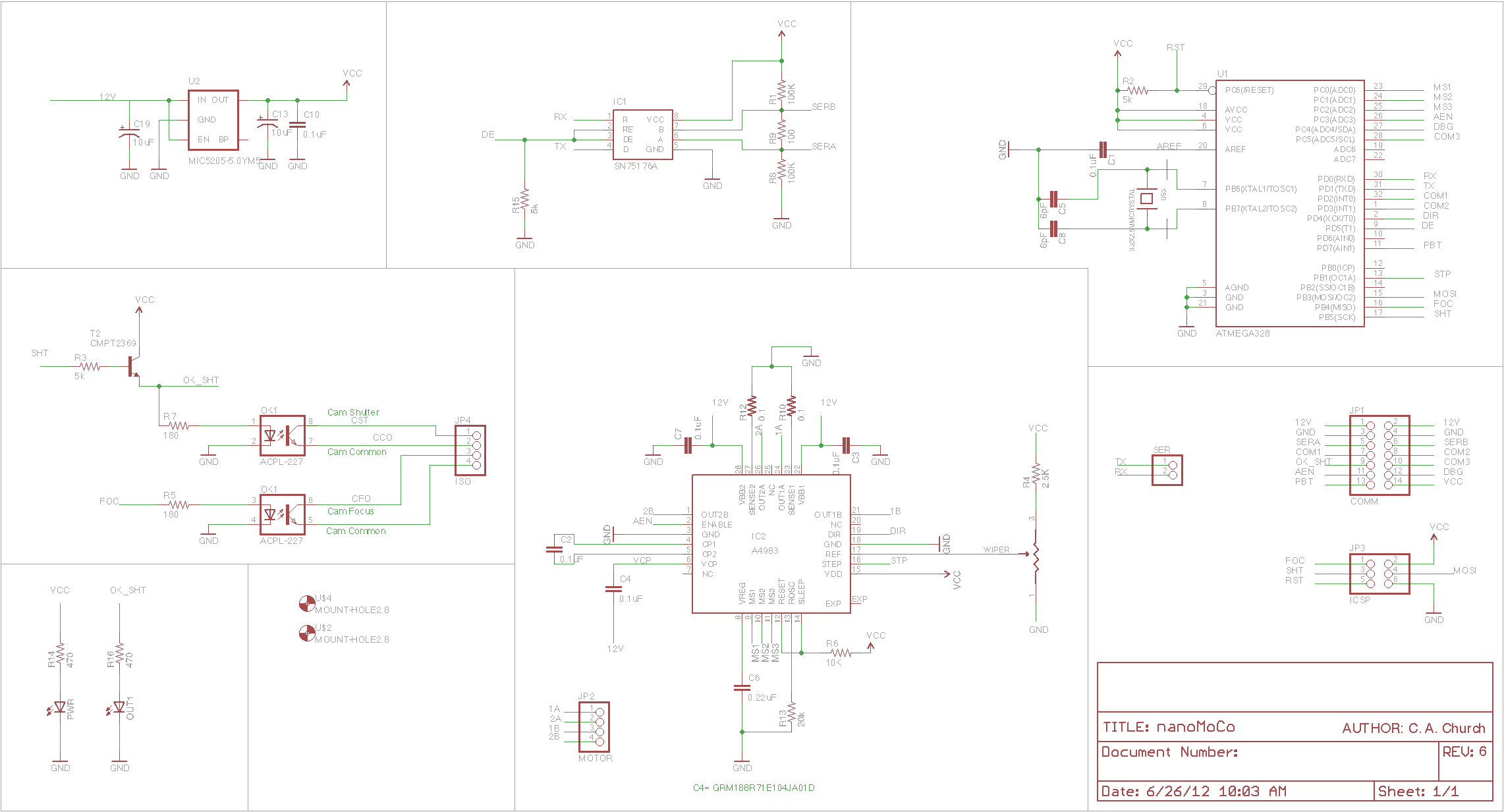
Note: up to date schematics can always be downloaded from the nanoMoCo Schematics and Board download page.
Using the nanoMoCo board with the Arduino IDE
The nanoMoCo board comes with pre-loaded both with a bootloader, and with a default firmware. The bootloader is a slightly modified form of the Optiboot bootloader used on most modern AVR-based Arduino devices. The modified source is included in the firmware source bundle.
This bootloader allows the upload of new firmware over the RS485 interface. You can use either the Arduino IDE or other standard tools such as AVRDude to upload new firmware images. To upload firmware, you will need a USB to RS485 converter, such as the FTDI USB-RS485-WE-1800-BT cable, or the Sparkfun USB to RS485 converter. (Please note: the RJ45 pinout on the Sparkfun converter does NOT match the required pinout for MoCoBus.) These devices will show up as a normal serial interface to your system, and allow you to interact directly with the nanoMoCo boards.
Uploading New Firmware with Arduino
The bootloader installed on the nanoMoCo boards will wait for 8 seconds after a power-cycle or hardware reset for a new firmware upload to start. After this 8 seconds have passed, no firmware upload can be initiated.
To upload firmware to the nanoMoCo using the Arduino IDE, first connect the A and B lines of your USB to RS485 converter to the A and B lines on the nanoMoCo. In the Arduino IDE, select the device type as "Arduino Uno", then reset or power-on the nanoMoCo and press the upload button.
During upload, the red and green LEDs on the FTDI cable will light. If only the red LEDs light, ensure your connections to the nanoMoCo are correct, and that you started uploading within 8 seconds of a power-on or hardware reset.
You may only have one device attached to the bus during firmware upload. Firmware uploading will not work correctly if more than one device is on the bus during the upload process.
Loading a New Bootloader
The nanoMoCo features a 6-pin ISP header consistent with that of standard Arduino boards. You can upload a new bootloader to the board using an ISP programmer in the same fashion as you would any Arduino board.
During ISP programming, the Output 1 LED will light, this is normal and indicative of correct operation.
related products - Related Products
- Log in to post comments